NAT:-
Network Address Translation (NAT) is a process in which one or more local IP address is translated into one or more Global IP address and vice versa in order to provide Internet access to the local hosts. Also, it does the translation of port numbers i.e. masks the port number of the host with another port number, in the packet that will be routed to destination. It then makes the corresponding entries of IP address and port number in the NAT table. NAT generally operates on router or firewall.
PROCEDURE (for Static):-
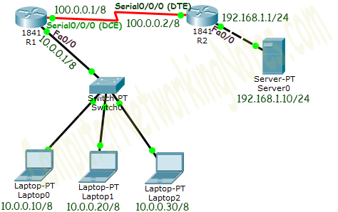
1) Take two routers and 4 PC's.
2) Connect 2 PC's each with switches and connect to with router. Then connect the routers.
3) Assign the IP, subnet mask and gateway.
Router 1 (Fa 0/0)............. 10.0.0.1 255.0.0.0 ---------
Router 1 (Se 2/0)............. 10.0.0.1 255.0.0.0 ---------
Router 2 (Fa 0/0)............. 192.168.1.1 255.255.255.0 ---------
Router 2 (Se 2/0)............. 100.0.0.20 255.0.0.0 ---------
PC 1 .............. 10.0.0.10 255.0.0.0 10.0.0.1
PC 2 .............. 10.0.0.20 255.0.0.0 10.0.0.1
PC 3 .............. 192.168.1.10 255.255.255.0 192.168.1.1
PC 4 .............. 192.168.1.20 255.255.255.0 192.168.1.1
Then write the command in each router after 'config' command in each of the router.
Router(config)# if not inside router static[inside local IP address] [inside global address]
Network Address Translation (NAT) is a process in which one or more local IP address is translated into one or more Global IP address and vice versa in order to provide Internet access to the local hosts. Also, it does the translation of port numbers i.e. masks the port number of the host with another port number, in the packet that will be routed to destination. It then makes the corresponding entries of IP address and port number in the NAT table. NAT generally operates on router or firewall.
PROCEDURE (for Static):-
1) Take two routers and 4 PC's.
2) Connect 2 PC's each with switches and connect to with router. Then connect the routers.
3) Assign the IP, subnet mask and gateway.
Router 1 (Fa 0/0)............. 10.0.0.1 255.0.0.0 ---------
Router 1 (Se 2/0)............. 10.0.0.1 255.0.0.0 ---------
Router 2 (Fa 0/0)............. 192.168.1.1 255.255.255.0 ---------
Router 2 (Se 2/0)............. 100.0.0.20 255.0.0.0 ---------
PC 1 .............. 10.0.0.10 255.0.0.0 10.0.0.1
PC 2 .............. 10.0.0.20 255.0.0.0 10.0.0.1
PC 3 .............. 192.168.1.10 255.255.255.0 192.168.1.1
PC 4 .............. 192.168.1.20 255.255.255.0 192.168.1.1
Then write the command in each router after 'config' command in each of the router.
Router(config)# if not inside router static[inside local IP address] [inside global address]
- Then define NAT inside from which the PC's are connected.
- Here, fast Ethernet 0/0.
- Router (Config-if)# if not inside.
- Then write the command router (config-if)# IP not outside from where the connection will go to outside world.
- Now configure static routing between Router 1 and Router 2, here we need RIP.
- Now, ping from the PC through their inside global IP address.
Comments
Post a Comment