
Implementation of DHCP Protocol

Dynamic Host Configuration Protocol(DHCP) is an application layer protocol which is used to provide:
  1. Subnet Mask (Option 1 – e.g., 255.255.255.0)
  2. Router Address (Option 3 – e.g., 192.168.1.1)
  3. DNS Address (Option 6 – e.g., 8.8.8.8)
  4. Vendor Class Identifier (Option 43 – e.g., ‘unifi’ = 192.168.1.9 ##where unifi = controller)
DHCP is based on a client-server model and based on discovery, offer, request, and ACK.
DHCP port number for server is 67 and for the client is 68. It is a Client server protocol which uses UDP services. IP address is assigned from a pool of addresses. In DHCP, the client and the server exchange mainly 4 DHCP messages in order to make a connection, also called DORA process, but there are 8 DHCP messages in the process.
DHCP Packet Tracer Example Topology

Steps:
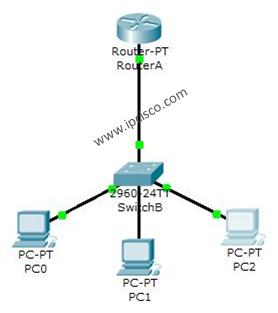
1) Create a network topology of a PC, a switch and a router.
2) The client is connected to Router-1, which acts like a DHCP server whose configuration         is discussed. When a client sens a DHCP request to the router then router sends any of       the available IPs to the router and assigns it.
3) Router Commands:
 Router>enable
 Router#config t
 Router(config)#int gig 0/1
 Router(config-if)# ip address 192.168.100.1    255.255.255.0
 Router(config-if)#no shut
 Router(config-if)#exit
 Router(config)#ip dhcp pool IP01
 Router(dhcp-config)#net 192.168.100.0 255.255.255.0
 Router(dhcp-config)# default 192.168.100.1
 Router(dhcp-config)#exit
 Router(config)#ip dhcp exc 192.168.100.1   192.168.100.15
 Router(config)#exit
 Router#
4) Then go to the PC and then click on DHCP icon in IP configuration.
5) Your PC will be issued an IP address with a message, "DHCP request successful"

Comments

Popular posts from this blog

Generate Traffic in Simulation Mode

Objectives Part 1: Generate Network Traffic in Simulation Mode Part 2: Examine the Functionality of the TCP and UDP Protocols Background This simulation activity is intended to provide a foundation for understanding the TCP and UDP in detail. Simulation mode provides the ability to view the functionality of the different protocols. As data moves through the network, it is broken down into smaller pieces and identified in some fashion so that the pieces can be put back together. Each of these pieces is assigned a specific name (protocol data unit [PDU]) and associated with a specific layer. Packet Tracer Simulation mode enables the user to view each of the protocols and the associated PDU. The steps outlined below lead the user through the process of requesting services using various applications available on a client PC.  This activity provides an opportunity to explore the functionality of the TCP and UDP protocols, multiplexing and the function of port numbers in ...

Socket Programming

SOCKET PROGRAMMING TCP SOCKET PROGRAMMING TCP  Python provides two levels of access to network services. At a low level, you can access the basic socket support in the underlying operating system, which allows you to implement clients and servers for both connection-oriented and connectionless protocols. Python also has libraries that provide higher-level access to specific application-level network protocols, such as FTP, HTTP, and so on. What is Sockets? Sockets are the endpoints of a bidirectional communications channel. Sockets may communicate within a process, between processes on the same machine, or between processes on different continents. Sockets may be implemented over a number of different channel types: Unix domain sockets, TCP, UDP, and so on. The socket library provides specific classes for handling the common transports as well as a generic interface for handling the rest. Sockets have their own vocabulary − Term & Description 1...

Configuring Routing Information Protocol

Routing Information Protocol  (RIP) It is a dynamic routing protocol which uses hop count as a routing metric to find the best path between the source and the destination network. It is a distance vector routing protocol which has AD value 120 and works on the application layer of OSI model. RIP uses port number 520. Steps: 1) Initially select 2 PCs,  2 Switches &  2 Routers namely, PC-1 & PC-2, Switch-1 &                Switch-2 and Router-1 & Router-2 respectively. 2) Make all the necessary connections using serial gateway 0/1, 3) Assign IP Addresses, Subnet Mask and Gateway as follows-      PC-1         192.168.2.1    255.255255.0      192.168.2.2      PC-2         192.168.3.1    255.255.255.0     192.168.3.2    Switch-1        ...